CYX19-32 series oil-filled core pressure sensor
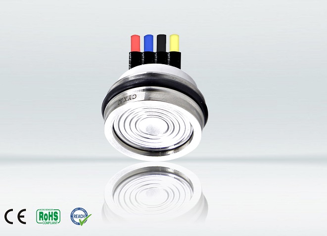
CYX19-32 series oil-filled core pressure sensor
55 customer reviews
The CYX series oil-filled core pressure sensors utilize internationally advanced, highly stable, and high-precision silicon pressure chips and employ a stress-optimized sintered base. They are manufactured through a process that includes surface mount assembly, gold wire bonding, diaphragm welding, high-vacuum oil filling, pressure cycling stress relief, high-temperature aging, and temperature compensation. Over thirty years of research, production experience, and process innovation have resulted in these products with exceptional stability and performance, earning widespread recognition from users.
1 Overview
The CYX series oil-filled core pressure sensors utilize internationally advanced, highly stable, and high-precision silicon pressure chips and employ a stress-optimized sintered base. They are manufactured through a process that includes surface mount assembly, gold wire bonding, diaphragm welding, high-vacuum oil filling, pressure cycling stress relief, high-temperature aging, and temperature compensation. Over thirty years of research, production experience, and process innovation have resulted in these products with exceptional stability and performance, earning widespread recognition from users.
1.1 Universal CYX19 oil-filled core pressure sensor
The appearance, assembly dimensions and sealing method of the universal product are consistent with those of similar international mainstream products, and have good interchangeability. They are widely used in pressure detection of media compatible with 316L stainless steel, nitrile rubber or fluororubber.
1.2 Chloride ion corrosion resistant CYX19 oil-filled core pressure sensor
The CYX19Ti oil-filled core pressure sensor shares the same appearance, assembly dimensions, and sealing configuration as the general-purpose CYX19 model. Its structure utilizes a new titanium alloy, with a housing constructed from the high-strength, corrosion-resistant TC4 material and a TA1 diaphragm. It is ideally suited for pressure measurement in media susceptible to chloride ion corrosion, such as seawater. Operating in humid atmospheres and seawater, its corrosion resistance far surpasses that of stainless steel, offering strong resistance to pitting, acid, and stress corrosion. It also exhibits excellent resistance to alkalis, chlorides, organic substances containing chlorine, nitric acid, and sulfuric acid. Its measurement range is -100kPa to 0kPa, 10kPa to 100MPa.
1. 3. Gauge pressure type CYX series oil-filled core pressure sensor for measuring negative pressure + Y after the model
Most types of oil-filled core pressure sensors, such as general-purpose ones, are produced using a special negative pressure process and can reliably complete detection below atmospheric pressure. The measuring range is arbitrarily selectable between -100kPa and 3MPa.
- Measuring range 0kPa~10kPa…100MPa
- Available in gauge pressure G, absolute pressure A and sealed gauge pressure S forms
- Constant current/constant voltage power supply
- Isolated structure, suitable for a variety of fluid media
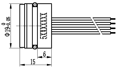
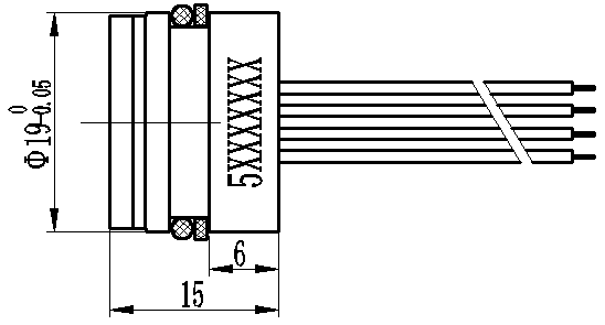
- Φ19mm standard OEM pressure oil injection core
- All 316L stainless steel
- Titanium structure optional, tantalum diaphragm customizable
- Power supply: ≤3.0mA; DC≤10V DC
- Electrical connection: 0.2mm 2 four-color 100mm silicone rubber soft wire
- Common mode voltage output: 50% (typical) of current type input, 40% (typical) of voltage type input
- Input impedance: 2.7kΩ~5kΩ
- Output impedance: 3.0kΩ~6kΩ
- Response time (10% to 90%): <1ms
- Insulation resistance: 500MΩ/100V DC
- Allowable overvoltage: 1.5 times full scale
- Diaphragm material: stainless steel 316L
- Titanium TA1 (CYX19Ti type)
- Shell material: stainless steel 316L
- Titanium TC4 (CYX19Ti type)
- Pressure pipe material: stainless steel 316L
- Pin leads: Gold-plated Kovar
- Sealing ring: Nitrile rubber, Fluororubber (optional)
- Net weight: about 23g (general type, CYX19Ti type)
- Vibration: No change at 10gRMS, (20~2000) Hz
- Constant acceleration: 100g, 11ms
- Media compatibility: 316L and NBR (optional FKM) liquids or gases
- Medium temperature: (25±3)℃
- Ambient temperature: (25±3)℃
- Humidity: (50% ± 10%) RH
- Ambient pressure: (86~106) kPa
- Power supply: (1.5±0.0015)mA DC
4.5 Standard range sensitivity output and optional pressure form
Range | Full scale Output (mV) | Pressure form |
| Range | Full scale Output (mV) | Pressure form |
0~10kPa | (30~120)±20 | G | 0~3.5MPa | (60~150)±20 | G/S/A | |
0~35kPa | (40~120)±20 | G/A | 0~6MPa | (60~130)±20 | S | |
0~70kPa | (20~140)±20 | G/A | 0~10MPa | (40~110)±20 | S | |
0~100kPa | (50~145)±20 | G/A | 0~25MPa | (30~110)±20 | S | |
0~200kPa | (30~125)±20 | G/A | 0~40MPa | (35~105)±20 | S | |
0~400kPa | (40~150)±20 | G/A | 0~60MPa | (70~165)±20 | S | |
0~1.0MPa | (55~145)±20 | G/A | 0~100MPa | (55~190)±20 | S | |
0~2.0MPa | (50~160)±20 | G/A |
|
|
|
|
Parameters | Typical values | Maximum | unit |
Full-scale output | 100 | 250 | mV |
Zero output | ±1 | ±2 | mV |
Nonlinear | 0.2 | 0.5 | %FS |
Hysteresis | 0.05 | 0.08 | %FS |
Repeatability | 0.05 | 0.08 | %FS |
Input/output impedance | 2.6 | 5.0 | kΩ |
Zero point temperature drift Note 1 | ±0.4 | ±1.0 | %FS,@25℃ |
Sensitivity temperature drift Note 2 | ±0.4 | ±1.0 | %FS, @25℃ |
Long-term stability | 0.2 | 0.3 | %FS/year |
Excitation current | 1.5 (the maximum input voltage is 10V) | mA | |
Insulation resistance | 500 (100VDC) | MΩ | |
Compensated Temperature Note 3 | 0~50;-10℃~70℃ | ℃ | |
Operating temperature | -40~+125 | ℃ | |
Storage temperature | -40~+125 | ℃ | |
Response time | ≤1 | ms | |
Housing and diaphragm materials | 316L stainless steel |
| |
O-ring | Fluororubber, nitrile rubber, silicone rubber |
| |
Measuring medium | Fluids compatible with 316L, Buna-N, Viton, or Silicone |
| |
Lifespan (25°C) | >1×10⁸ pressure cycles (80% FS) | Second-rate | |
Filling medium | silicone oil |
| |
sealing ring | Φ16×1.8mm (nitrile or fluorinated rubber Note 4) |
| |
Note 1, Note 2: 0~10kPa zero point temperature drift and sensitivity temperature drift typical value is 0.5%FS@25℃, maximum value is 1.2%FS@25℃. Note 3: For ranges up to 200 kPa, the compensation temperature is 0 to 50°C; for ranges greater than 200 kPa, the compensation temperature is -10°C to 70°C. Note 4: The temperature range of fluororubber sealing ring is -20℃~200℃, and its low temperature performance is poor. When the temperature range is lower than -20℃, please verify its use. | |||
5.1 Core selection model and appearance
series | Range | model | Dimensions |
CYX19 | -100kPa~10MPa | C YX1901 |
|
C YX1901P | 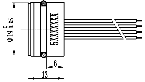 | ||
25MPa~100MPa | C YX190 2 |
| |
CYX32 | -100kPa~3.5MPa | C YX3201 | 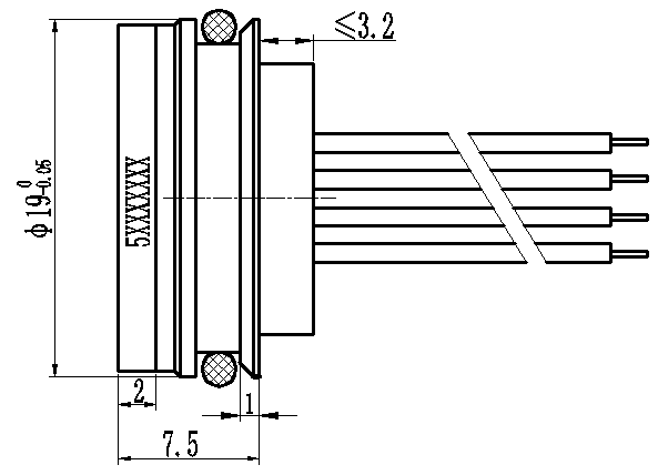 |
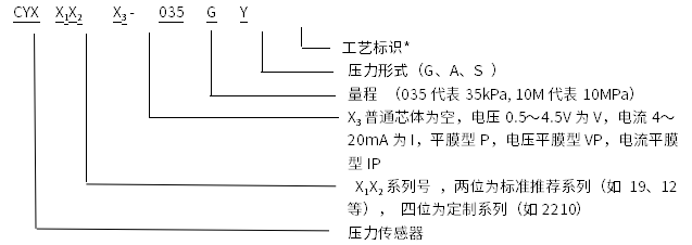
*Process identification: f represents general process, Y represents negative pressure process.
6 Schematic diagram and wiring method
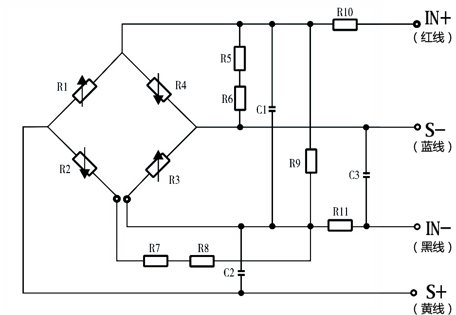
IN+ (red wire) - positive power supply IN- (black wire) - negative power supply S+ (yellow wire) - positive output S- (blue wire) - negative output
- The recommended sealing method for the pressure core is to use a "floating" sealing structure with a side wall O-ring to avoid compression of the front end surface and prevent affecting the stability of the pressure core.
- Pay attention to protecting the front diaphragm of the pressure core and the compensation circuit board at the rear end to avoid scratches that may affect the performance of the pressure core or cause damage to the core.
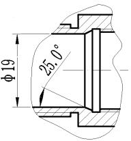
- The core cavity of the shell should be designed with a tapered angle as shown in the figure, which makes it easier to assemble the core and prevents the sealing ring from being scratched by right angles .
- During assembly, pay attention to the tolerance of the core size and the inner shell of the transmitter housing. It is recommended that the cavity be processed according to +0.02 to +0.05 of the core diameter to achieve the required airtightness.
- When assembling, place it vertically and press down evenly to prevent it from getting stuck or damaging the compensation piece.
- Do not press the metal diaphragm with your hands or hard objects to avoid damage to the core due to chip deformation or perforation.
- When wiring, the core pins should not be cut too short, the length should generally not be less than 5mm, and the welding time should not exceed 5 seconds.
- The vent pipe at the rear of the G-type core must remain connected to the atmosphere; water, water vapor or corrosive media are prohibited from entering the reference cavity at the rear of the core.
- Avoid dropping or bumping, which may affect the stability of the product.
- If there are any changes in the pin leads, please refer to the label on the actual core.

Gree Air Conditioner
$33.00
4.9

Pliers | Cutting, Gripping
$50.00
5.0

Gear and wrench
$33.00 $28.00
4.5

Nut Driver
$40.00
4.8