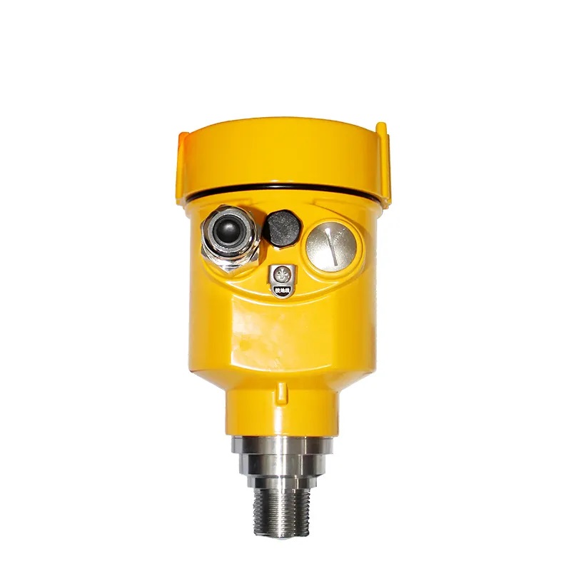
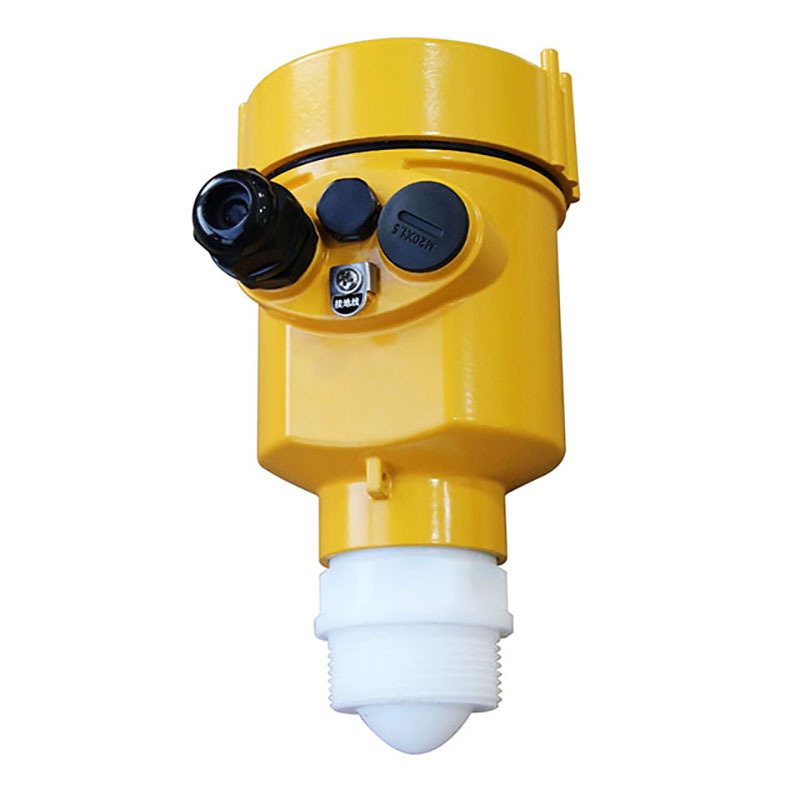
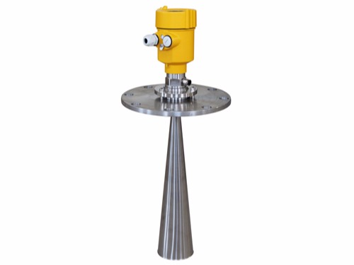
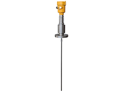
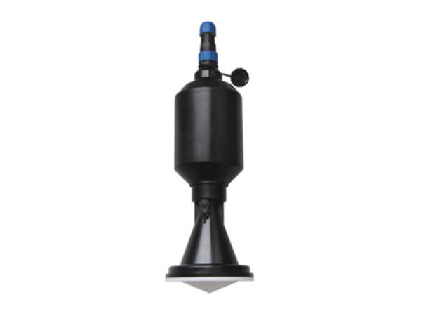
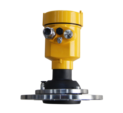
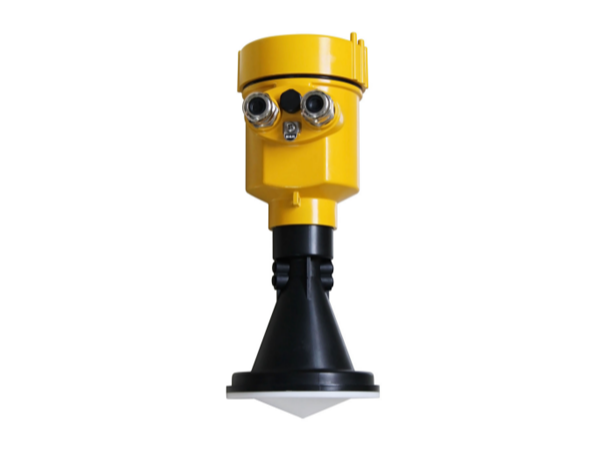
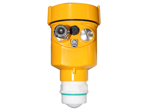
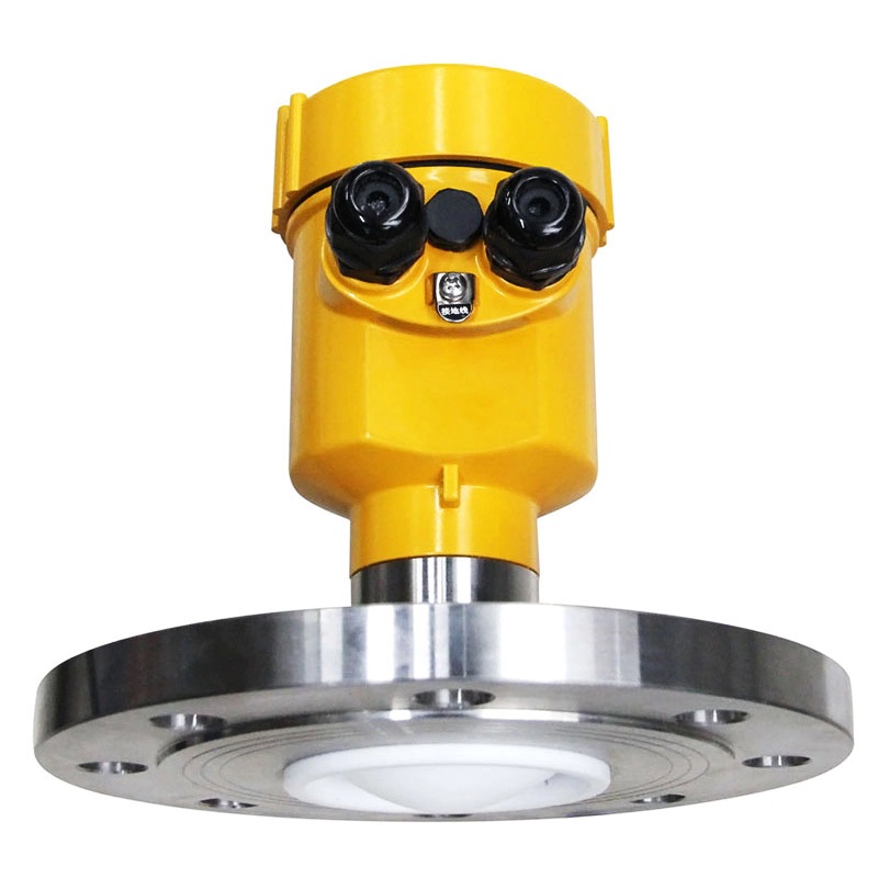
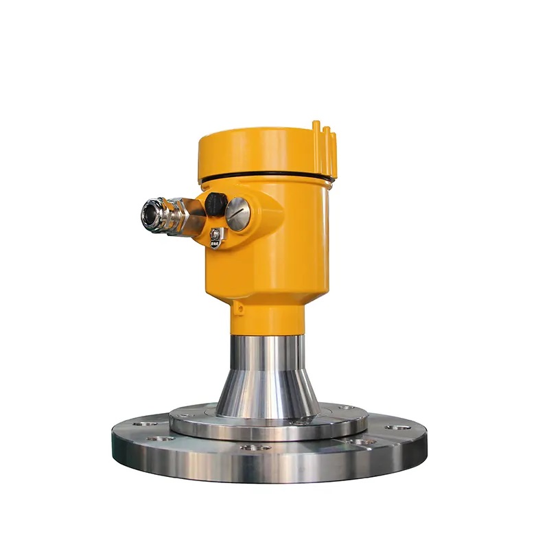
120GHz Radar Level Transmitter


120GHz Radar Level Transmitter
55 customer reviews
Application: Solids
Measuring Range?0.3m~150m
Protection Grade?IP67
Accuracy?± 5mm (range below 35m)
Frequency: 123GHz
Process Pressure?-0.1~0.3MPa
Process Temperature?-40~110?
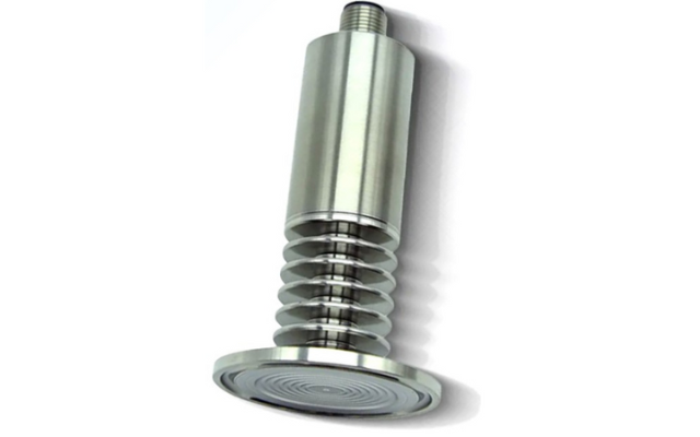
Process Connection?Flange ?DN80
Explosion proof certification:Exia IIC T6 Ga / Exd ia IIC T6 Gb / Ex ia D20 T85?
Outer Covering?Aluminum / Plastic / Stainless steel
: M20x1.5 1/2NPT
Power supply
1 Overview
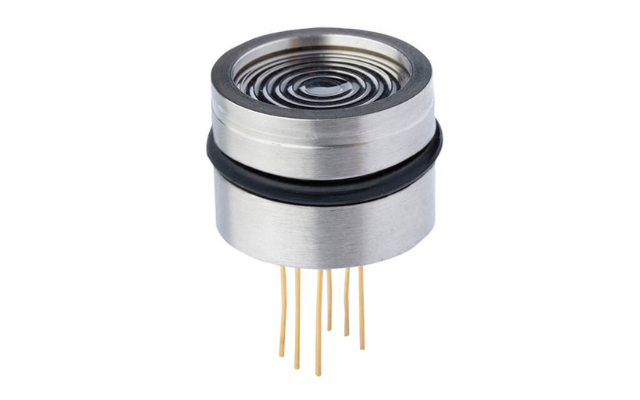
The FMCW radar level meter antenna transmits a frequency modulated continuous wave signal (76-81GHz) at the speed of light. On encountering the surface of the measured substance, part of its energy is reflected back into the same antenna. This echo signal mixed with the transmitted one results in an output intermediate frequency signal whose frequency is proportional to the distance from the antenna to the medium. Thus, calculating this distance becomes possible.The KD-FMF series sensor is a 120G frequency modulation radar type level measuring instrument with a measuring distance of up to 30 meters. The antenna is further optimized, and the new and fast microprocessor can perform higher-speed signal analysis and processing, so that the meter can be used for measuring high temperature and high pressure and other environmental liquids.
2 Product Principle
Grain gauge bin level indicator used in industry mainly have three bands, namely C-band, K-band, and W-band. The emission frequencies of different bands are different, and the product performance also varies.We produce millimeter-wave radar level meters in the W-band and 76-81GHz.
The general principle of the FM continuous wave radar level gauge is that the radar emits electromagnetic waves on the top of the tank, and the electromagnetic waves are received by the radar after being reflected by the medium. The frequency difference δ f between the received signal and the transmitted signal is proportional to the distance R from the surface of the medium. : R= C (speed) *δ f (frequency difference) /2/K (frequency modulation slope). Because the speed of light C and the frequency modulation slope K are known, the frequency difference δ f can be estimated to obtain the distance R of the material surface at the radar installation position, and then through the known total height of the tank, subtract the spatial distance from the radar to the material surface ( Referred to as the air height), the height of the material grain bin level indicator is obtained.
3 Protection Grade
This meter fully meets the requirements of protection class IP66/67, please ensure the waterproofness of the cable sealing head. As shown:
How to ensure that the installation meets the requirements of IP67:
Make sure that the sealing head is not damaged.
Make sure that the cable is not damaged.
Make sure that the cables used meet the requirements of the electrical connection specifications.
Before entering the electrical interface, bend the cable downward to ensure that water does not flow into the housing, see ①
Please tighten the cable sealing head, see ②
Please block the unused electrical interfaces with blind plugs, see ③
4 Product Specification
Measuring medium: solid
Measuring range: 0.3m~120m
Process connection: flange ≥DN80
Process temperature: -40~110℃
Process pressure: -0.1~0.3MPa
Precision: ±5mm
Protection level: IP67
Frequency range: 120GHz
Power supply: two-wire system (DC24V)/four-wire system (DC12V~24V)/four-wire system (AC220V)
Explosion-proof grade: Exia ⅡC T6 Ga / Exd IIC T6 Gb
Housing: Aluminum/Plastic/Stainless Steel
Signal output: two-wire system 4…20mA/HART protocol/four-wire system 4…